info@gerb.com
Viscous Dampers to reduce vibrations in Piping Systems in a Petrochemical Plant
GERB was approached by a petrochemical company from the middle east region to help mitigate vibration problems from one of their amine plants
In total 4 units needed to be solved as vibration level exceeded allowable limits (see Figure 1). The customers internal process study revealed that there is slug flow in the piping which induces internal forces which cannot be eliminated. Considering the limitations like large bore (36”) piping, long vertical runs and the fact that most of the supports are attached to a pressure vessel, it is not feasible to modify the pipe routing or existing supports. GERB pipework dampers are a good solution for such problems because of their excellent retrofit characteristics and generally strong vibration reduction capabilities. The goal was to reduce the classification level from “Concern” to “Acceptable” at the locations 6 and 7 at the first installation unit (similar but slightly different points at the other units).

Model Creation and Simulation
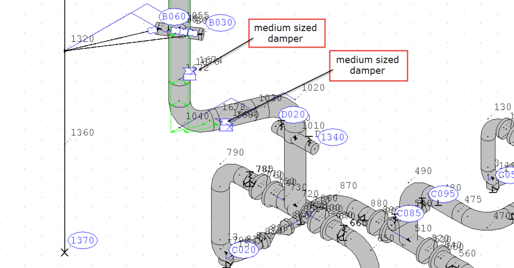
The customer provided CEASAR II model data which was imported into Rohr2. See Figure 2 for an overview of the piping system and Figure 3 for installation idea with dampers.

To get an understanding of the impact different damper setups were checked, e.g. two or four dampers per piping section. Figure 3 shows the system with two dampers installed.
Please see [1] for a detailed explanation about the modelling of viscous dampers or [2] for a more specific explanation on how to use this in piping applications.
Simulation Results
The following setups were compared:
- Without dampers
- With two dampers
- With four dampers (two dampers in each location in tandem arrangement)
It is visible that substantial vibration reduction can be achieved for Node 1010 and Node 1050 which are close to the damper installation locations. For Node 1060 which is further away from the damper installation location the reduction effect is reduced.

Damper Selection
The number of dampers were selected to achieve the best possible amount of damping reduction, according to local conditions for installation and support capabilities:
- Maximum forces on supports should not exceed 5 kN
- Suitable support installation points were limited
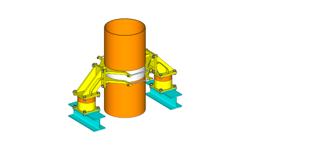
It was decided to install a total of 4 medium sized dampers at this installation unit. The damper size was selected to reduce the requirements for necessary strength and stiffness of the local supports. It was also decided to install the dampers in a so-called tandem arrangement to reduce the possible amount of torque on the supports and the piping itself. Figure 7 shows a picture of such an installation scheme.
Friction Clamp Design
The customer asked GERB to also provide the complicated friction clamp design and manufacturing for this tandem arrangement. In the design phase topics like friction capability, thermal expansion and corrosion protection due to stainless steel piping and carbon steel clamps had to be considered. Below is an abbreviated list of the requirements:
- 30 inch stainless steel pipe
- Carbon steel clamp in tandem arrangement
- Operating temperature fluid 107° C
- +5° C … +55° C ambient temperature
- All necessary damper forces needed to be transferred via friction forces of the clamp
- All components must conform necessary strength requirements of applicable standards and codes
- Useful installation possibilities at higher levels of the plant
To prevent contact corrosion a stainless steel inlay was designed to be put between the clamp and the pipe. The clamp itself is from S355. Futhermore the design can accommodate for the above listed requirements while at the same time the design is not expensive and not difficult to install.
Manufacturing
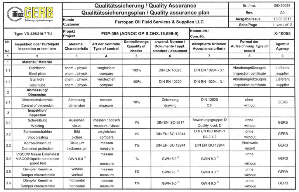
The entire manufacturing of the dampers and the clamps was performed at the GERB headquarter in Berlin, Germany. Quality monitoring and documentation of production was carried out using valid standards and a detailed Quality Assurance Plan (QAP) agreed with the customer (see Figure 8). Manufacturing was done in time and the parts delivered to the customer.
Installation and Supervision
The installation process was done in cooperation with the final customer. A crane as well as installation personnel was provided by the customer. The installation process itself was supervised by an experienced GERB engineer on site. A quality manual provided in detail explanations about all required installation steps.
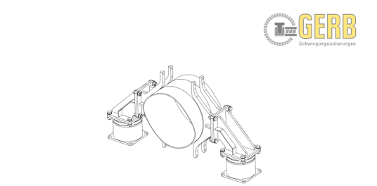
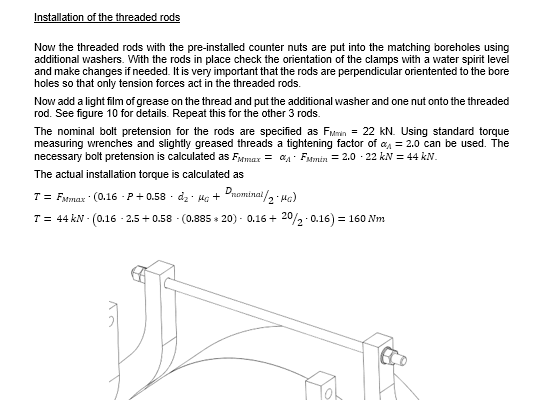
Figure 9 and 10 show a page from this installation manual to give an impression. [3] is a reference to the GERB standard installation manual for dampers. Each clamp installation gets a specific manual created precisely for that installation scheme.
Measured Confirmation
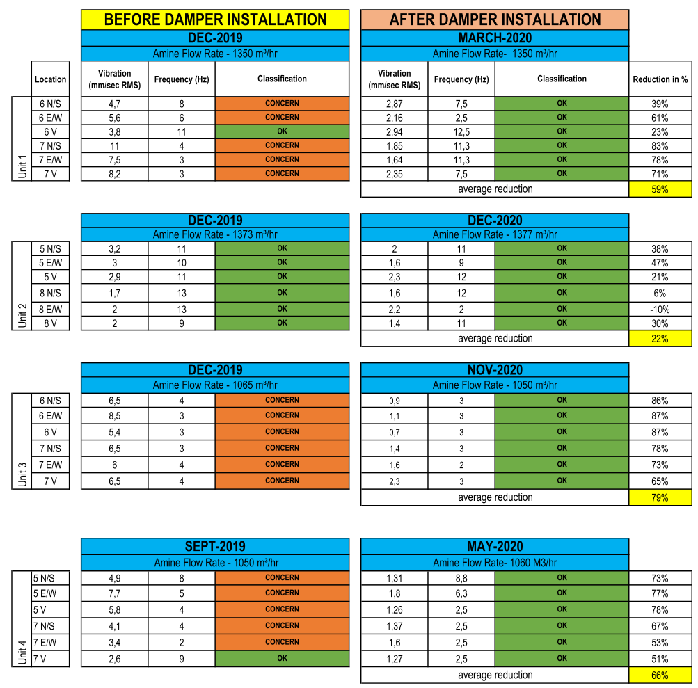
Table 2 shows the results from the situation at the 4 different units before the dampers were installed and with dampers installed. Except for system 2 – which was without concern from the beginning – all systems could be reduced from “Concern”-levels to “Acceptable”-levels. The average reduction was in the range between roughly 60% and 80% with an overall average of 68% (for system 1, 3 and 4). This is about 20% more than the simulation had anticipated with an average reduction of about 45%.
This is a high average reduction value which indicates that the planning, selection, manufacturing and installation of the dampers was performed in a correct manner.
Conclusion
This case study shows that the use of viscous pipework dampers can be very efficient to reduce operational vibrations in piping systems with slug flow and similar phenomena. The described installation is very cost efficient and could be installed with the entire plant running. This reduces the downtime of the plant as well as additional costs due to outage.
The average reduction of roughly 68% is more than the simulation calculated and indicates some conservatism in the modelling approach. At the same time it shows that the planning of the support point preparations and the general installation was performed in a professional manner which is needed to achieve best possible damper performance. All project-related parameters were considered in the design of the damper and connecting components. This underlines that simulation and usage of pipework dampers is a feasible and cost-efficient tool in the mitigation of vibrations in petro-chemical plants.
REFERENCES
[1] Description of the frequency dependent characteristics of viscous elastic Dampers
Barutzki, GERB, December 2006, pdf
[2] Improving Service Life and Safety of Piping Systems by the use of Viscous Dampers, for Middle East Static Convention 2018
Fischer, Barutzki, GERB, March 2018, pdf
[3] Instructions for Transport, Installation, Maintenance and Disposal for all types of Pipework Dampers
Fischer, Barutzki, GERB, April 2020, pdf
Please feel free to contact us regarding above mentioned references.
Further Resources
You need further information on this topic?
Please do not hesitate to contact us with your individual question.
One of our project engineers will get back to you shortly.
Viscous Dampers to reduce vibrations in Piping Systems in a Petrochemical Plant
GERB was approached by a petrochemical company from the middle east region to help mitigate vibration problems from one of their amine plants
In total 4 units needed to be solved as vibration level exceeded allowable limits (see Figure 1). The customers internal process study revealed that there is slug flow in the piping which induces internal forces which cannot be eliminated. Considering the limitations like large bore (36”) piping, long vertical runs and the fact that most of the supports are attached to a pressure vessel, it is not feasible to modify the pipe routing or existing supports. Gerb pipework dampers are a good solution for such problems because of their excellent retrofit characteristics and generally strong vibration reduction capabilities. The goal was to reduce the classification level from “Concern” to “Acceptable” at the locations 6 and 7 at the first installation unit (similar but slightly different points at the other units).

Model Creation and Simulation
The customer provided CEASAR II model data which was imported into Rohr2. See Figure 2 for an overview of the piping system and Figure 3 for installation idea with dampers.

To get an understanding of the impact different damper setups were checked, e.g. two or four dampers per piping section. Figure 3 shows the system with two dampers installed. Please see [1] for a detailed explanation about the modelling of viscous dampers or [2] for a more specific explanation on how to use this in piping applications.

Simulation Results
The following setups were compared:
- Without dampers
- With two dampers
- With four dampers (two dampers in each location in tandem arrangement)
It is visible that substantial vibration reduction can be achieved for Node 1010 and Node 1050 which are close to the damper installation locations. For Node 1060 which is further away from the damper installation location the reduction effect is reduced.

Damper Selection
The number of dampers were selected to achieve the best possible amount of damping reduction, according to local conditions for installation and support capabilities:
- Maximum forces on supports should not exceed 5 kN
- Suitable support installation points were limited
It was decided to install a total of 4 medium sized dampers at this installation unit. The damper size was selected to reduce the requirements for necessary strength and stiffness of the local supports. It was also decided to install the dampers in a so-called tandem arrangement to reduce the possible amount of torque on the supports and the piping itself. Figure 7 shows a picture of such an installation scheme.

Friction Clamp Design
The customer asked GERB to also provide the complicated friction clamp design and manufacturing for this tandem arrangement. In the design phase topics like friction capability, thermal expansion and corrosion protection due to stainless steel piping and carbon steel clamps had to be considered. Below is an abbreviated list of the requirements:
- 30 inch stainless steel pipe
- Carbon steel clamp in tandem arrangement
- Operating temperature fluid 107° C
- +5° C … +55° C ambient temperature
- All necessary damper forces needed to be transferred via friction forces of the clamp
- All components must conform necessary strength requirements of applicable standards and codes
- Useful installation possibilities at higher levels of the plant
To prevent contact corrosion a stainless steel inlay was designed to be put between the clamp and the pipe. The clamp itself is from S355. Futhermore the design can accommodate for the above listed requirements while at the same time the design is not expensive and not difficult to install.
Manufacturing
The entire manufacturing of the dampers and the clamps was performed at the GERB headquarter in Berlin, Germany. Quality monitoring and documentation of production was carried out using valid standards and a detailed Quality Assurance Plan (QAP) agreed with the customer (see Figure 8). Manufacturing was done in time and the parts delivered to the customer.

Installation and Supervision
The installation process was done in cooperation with the final customer. A crane as well as installation personnel was provided by the customer. The installation process itself was supervised by an experienced GERB engineer on site. A quality manual provided in detail explanations about all required installation steps.
Figure 9 and 10 show a page from this installation manual to give an impression. [3] is a reference to the GERB standard installation manual for dampers. Each clamp installation gets a specific manual created precisely for that installation scheme.


Measured Confirmation
Table 2 shows the results from the situation at the 4 different units before the dampers were installed and with dampers installed. Except for system 2 – which was without concern from the beginning – all systems could be reduced from “Concern”-levels to “Acceptable”-levels. The average reduction was in the range between roughly 60% and 80% with an overall average of 68% (for system 1, 3 and 4). This is about 20% more than the simulation had anticipated with an average reduction of about 45%.
This is a high average reduction value which indicates that the planning, selection, manufacturing and installation of the dampers was performed in a correct manner.

Conclusion
This case study shows that the use of viscous pipework dampers can be very efficient to reduce operational vibrations in piping systems with slug flow and similar phenomena. The described installation is very cost efficient and could be installed with the entire plant running. This reduces the downtime of the plant as well as additional costs due to outage.
The average reduction of roughly 68% is more than the simulation calculated and indicates some conservatism in the modelling approach. At the same time it shows that the planning of the support point preparations and the general installation was performed in a professional manner which is needed to achieve best possible damper performance. All project-related parameters were considered in the design of the damper and connecting components. This underlines that simulation and usage of pipework dampers is a feasible and cost-efficient tool in the mitigation of vibrations in petro-chemical plants.
Model Creation and Simulation
The customer provided CEASAR II model data which was imported into Rohr2. See Figure 2 for an overview of the piping system and Figure 3 for installation idea with dampers.

To get an understanding of the impact different damper setups were checked, e.g. two or four dampers per piping section. Figure 3 shows the system with two dampers installed.

Simulation Results
The following setups were compared:
- Without dampers
- With two dampers
- With four dampers (two dampers in each location in tandem arrangement)
It is visible that substantial vibration reduction can be achieved for Node 1010 and Node 1050 which are close to the damper installation locations. For Node 1060 which is further away from the damper installation location the reduction effect is reduced.

Damper Selection
The number of dampers were selected to achieve the best possible amount of damping reduction, according to local conditions for installation and support capabilities:
- Maximum forces on supports should not exceed 5 kN
- Suitable support installation points were limited
It was decided to install a total of 4 medium sized dampers at this installation unit. The damper size was selected to reduce the requirements for necessary strength and stiffness of the local supports. It was also decided to install the dampers in a so-called tandem arrangement to reduce the possible amount of torque on the supports and the piping itself. Figure 7 shows a picture of such an installation scheme.

Friction Clamp Design
The customer asked GERB to also provide the complicated friction clamp design and manufacturing for this tandem arrangement. In the design phase topics like friction capability, thermal expansion and corrosion protection due to stainless steel piping and carbon steel clamps had to be considered. Below is an abbreviated list of the requirements:
- 30 inch stainless steel pipe
- Carbon steel clamp in tandem arrangement
- Operating temperature fluid 107° C
- +5° C … +55° C ambient temperature
- All necessary damper forces needed to be transferred via friction forces of the clamp
- All components must conform necessary strength requirements of applicable standards and codes
- Useful installation possibilities at higher levels of the plant
To prevent contact corrosion a stainless steel inlay was designed to be put between the clamp and the pipe. The clamp itself is from S355. Futhermore the design can accommodate for the above listed requirements while at the same time the design is not expensive and not difficult to install.
Manufacturing
The entire manufacturing of the dampers and the clamps was performed at the GERB headquarter in Berlin, Germany. Quality monitoring and documentation of production was carried out using valid standards and a detailed Quality Assurance Plan (QAP) agreed with the customer (see Figure 8). Manufacturing was done in time and the parts delivered to the customer.

Installation and Supervision
The installation process was done in cooperation with the final customer. A crane as well as installation personnel was provided by the customer. The installation process itself was supervised by an experienced GERB engineer on site. A quality manual provided in detail explanations about all required installation steps.
Figure 9 shows a page from this installation manual to give an impression. [3] is a reference to the GERB standard installation manual for dampers. Each clamp installation gets a specific manual created precisely for that installation scheme.


Measured Confirmation
Table 2 shows the results from the situation at the 4 different units before the dampers were installed and with dampers installed. Except for system 2 – which was without concern from the beginning – all systems could be reduced from “Concern”-levels to “Acceptable”-levels. The average reduction was in the range between roughly 60% and 80% with an overall average of 68% (for system 1, 3 and 4). This is about 20% more than the simulation had anticipated with an average reduction of about 45%.
This is a high average reduction value which indicates that the planning, selection, manufacturing and installation of the dampers was performed in a correct manner.

Conclusion
This case study shows that the use of viscous pipework dampers can be very efficient to reduce operational vibrations in piping systems with slug flow and similar phenomena. The described installation is very cost efficient and could be installed with the entire plant running. This reduces the downtime of the plant as well as additional costs due to outage.
The average reduction of roughly 68% is more than the simulation calculated and indicates some conservatism in the modelling approach. At the same time it shows that the planning of the support point preparations and the general installation was performed in a professional manner which is needed to achieve best possible damper performance. All project-related parameters were considered in the design of the damper and connecting components. This underlines that simulation and usage of pipework dampers is a feasible and cost-efficient tool in the mitigation of vibrations in petro-chemical plants.
REFERENCES
[1] Description of the frequency dependent characteristics of viscous elastic Dampers
Barutzki, GERB, December 2006, pdf
[2] Improving Service Life and Safety of Piping Systems by the use of Viscous Dampers, for Middle East Static Convention 2018
Fischer, Barutzki, GERB, March 2018, pdf
[3] Instructions for Transport, Installation, Maintenance and Disposal for all types of Pipework Dampers
Fischer, Barutzki, GERB, April 2020, pdf
Please feel free to contact us regarding above mentioned references.
Share this post
Further Resources
You need further information on this topic?
Please do not hesitate to contact us with your individual question.
One of our project engineers will get back to you shortly.
Further Resources
You need further information on this topic?
Please do not hesitate to contact us with your individual question.
One of our project engineers will get back to you shortly.